CPRE 5450 · Fault Tolerant Systems · Iowa State University, Spring 2026

Fault-Tolerant
Presence Verification
on ESP32-S3

A health-aware activation controller using 24 GHz mmWave radar and on-device vision to decide — dependably — when a privacy-sensitive assistive system is allowed to activate.

Shobhit Singh ESP32-S3 · FreeRTOS · ESP-IDF v5 24 GHz FMCW mmWave + OV2640 7-state fault-tolerant FSM Fault injection evaluation
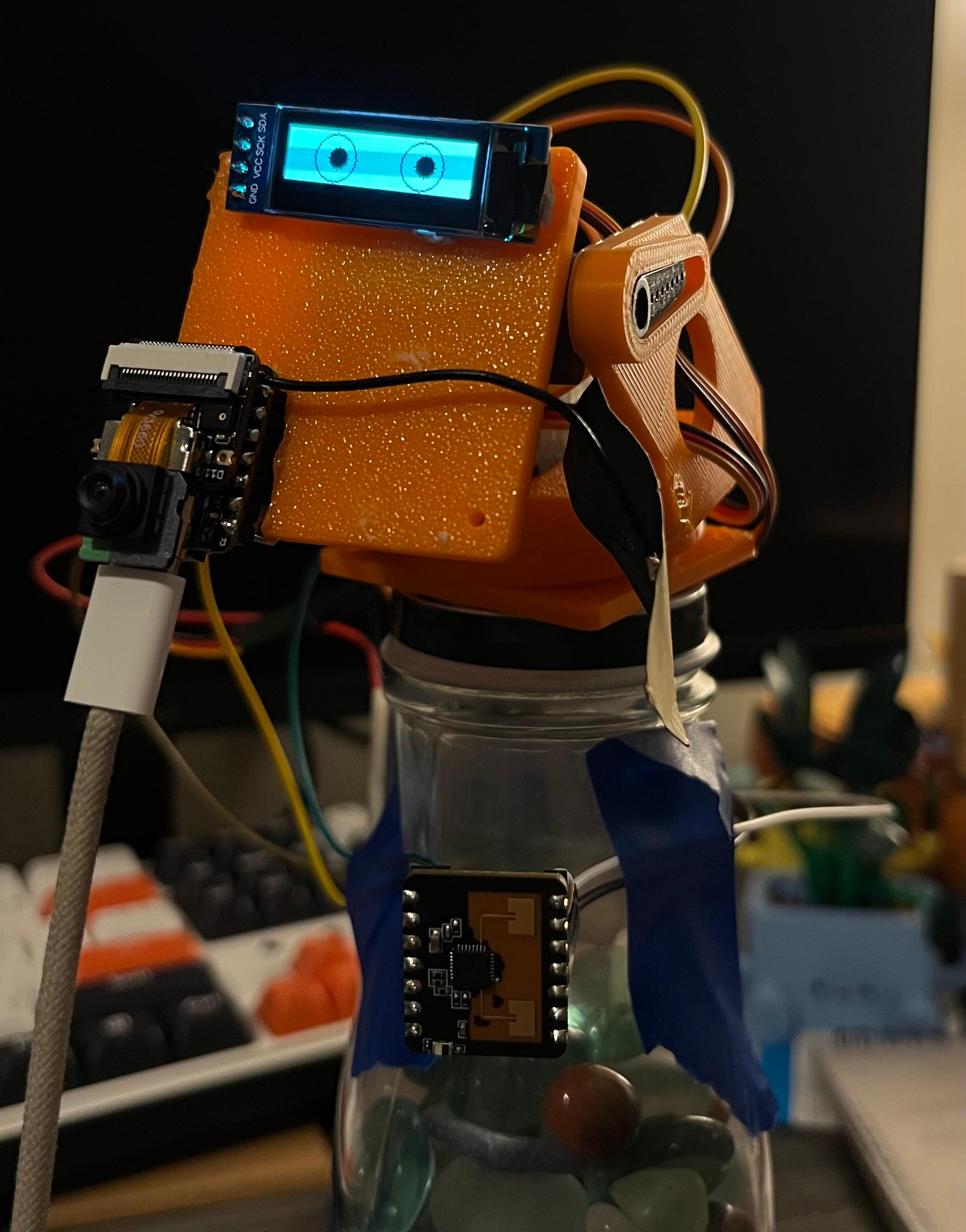
MIRA 2.0 robot: 3D-printed body, OLED eyes, camera, and mmWave sensor

Why activation matters

Room-scale assistive systems must decide when to wake up, when to sense, and when to interact. This is especially critical in privacy-preserving systems for blind or visually impaired (BVI) users: unnecessary camera or audio activation can expose private data, while missed activation can deny assistance at a critical moment.

CPRE 5450 scope. This project isolates one dependability-critical subsystem from the larger CPRE 5750 MIRA platform — the activation and presence-verification layer. The central question: "When is the system allowed to activate high-power or privacy-sensitive functions such as camera inference, audio capture, or servo actuation?"
Figure 1 — Project Scope: What CPRE 5450 Addresses
flowchart TD
    A["Broader CPRE 5750 Project\nPrivacy-Preserving Multimodal Assistant"] --> B["Full System Components"]
    B --> B1["ESP32-S3 Sense\ncamera + microphone"]
    B --> B2["24 GHz mmWave\npresence sensing"]
    B --> B3["Pan-tilt servos\nuser tracking"]
    B --> B4["Gesture recognition\nopen palm / closed fist"]
    B --> B5["Android offload\nspeech + object recognition"]
    A --> C["CPRE 5450 Focus\nFault-Tolerant Activation Subsystem"]
    C --> C1["Presence verification"]
    C --> C2["Camera activation decision"]
    C --> C3["Cross-sensor consistency checking"]
    C --> C4["Safe-state policy"]
    C --> C5["Fault injection evaluation"]
    C1 --> D["Question Studied:\nWhen is the assistant allowed to wake up, sense, and interact?"]
    classDef main fill:#e8f2ff,stroke:#2b6cb0,stroke-width:2px,color:#111;
    classDef focus fill:#fff4e6,stroke:#c05621,stroke-width:2px,color:#111;
    classDef item fill:#f7fafc,stroke:#718096,color:#111;
    class A,C,D main;
    class B,B1,B2,B3,B4,B5,C1,C2,C3,C4,C5 item;
      
This is not only a sensor-fusion problem — it is a fault-tolerant decision problem. The subsystem must remain reliable under sensor faults, timing faults, and environmental uncertainty.

Failure modes

A single-modality activation scheme is brittle — each sensor has different failure conditions. The two major system-level failure modes are:

False Activation

Camera / radar disagrees → system activates anyway

The system activates camera, audio, or actuation even though no valid user is present. Wastes battery and may compromise privacy.

Missed Activation

System fails to activate when needed

The system fails to activate even though the user is present and needs interaction — a denial-of-service failure for an assistive system.

Fault–Error–Failure Chain

Fault SourceError State System FailureConsequence
Low light / occlusion Camera false negative Missed activation No assistance to user
Fan / curtain / reflection Radar false positive False activation Battery drain + privacy risk
UART packet drop Stale radar state Wrong decision Unsafe or unavailable behavior
ESP32 task delay Old camera frame used Silent wrong decision Hard-to-detect reliability failure
Figure 2 — Fault–Error–Failure Chain
flowchart LR
    F["Fault Source"] --> E["Error State"] --> Y["System-Level Failure"] --> C["Consequence"]
    F1["Low light / occlusion"] --> E1["Camera false negative"] --> Y1["Missed activation"] --> C1["No assistance to user"]
    F2["Fan / curtain / reflection"] --> E2["Radar false positive"] --> Y2["False activation"] --> C2["Battery drain + privacy risk"]
    F3["UART packet drop"] --> E3["Stale radar state"] --> Y3["Wrong activation decision"] --> C3["Unsafe or unavailable behavior"]
    F4["ESP32 task delay"] --> E4["Old camera frame used"] --> Y4["Silent incorrect decision"] --> C4["Hard-to-detect reliability failure"]
    classDef source fill:#fff5f5,stroke:#c53030,color:#111;
    classDef error fill:#fffaf0,stroke:#dd6b20,color:#111;
    classDef fail fill:#fefcbf,stroke:#d69e2e,color:#111;
    classDef cons fill:#edf2f7,stroke:#4a5568,color:#111;
    class F,F1,F2,F3,F4 source;
    class E,E1,E2,E3,E4 error;
    class Y,Y1,Y2,Y3,Y4 fail;
    class C,C1,C2,C3,C4 cons;
      

Components & constraints

ComponentPartSpecification
MCU Seeed XIAO ESP32-S3 Sense Dual-core Xtensa LX7 @ 240 MHz, 512 KB SRAM, 8 MB PSRAM, 8 MB flash
Camera OmniVision OV2640 DVP 8-bit, 240×240 RGB565, ~10 fps effective with inference
mmWave sensor Seeed MR24HPC1 (24 GHz FMCW) UART 115200 8N1, 0.75–6 m range, ±60°, moving + stationary detection
Display SSD1306 OLED (I2C) "Eyes" bitmap, status feedback
Audio I2S MEMS microphone Async capture, I2S DMA
Pan-tilt 2× servo (PWM/LEDC) User-tracking actuation

mmWave sensor — radar configuration

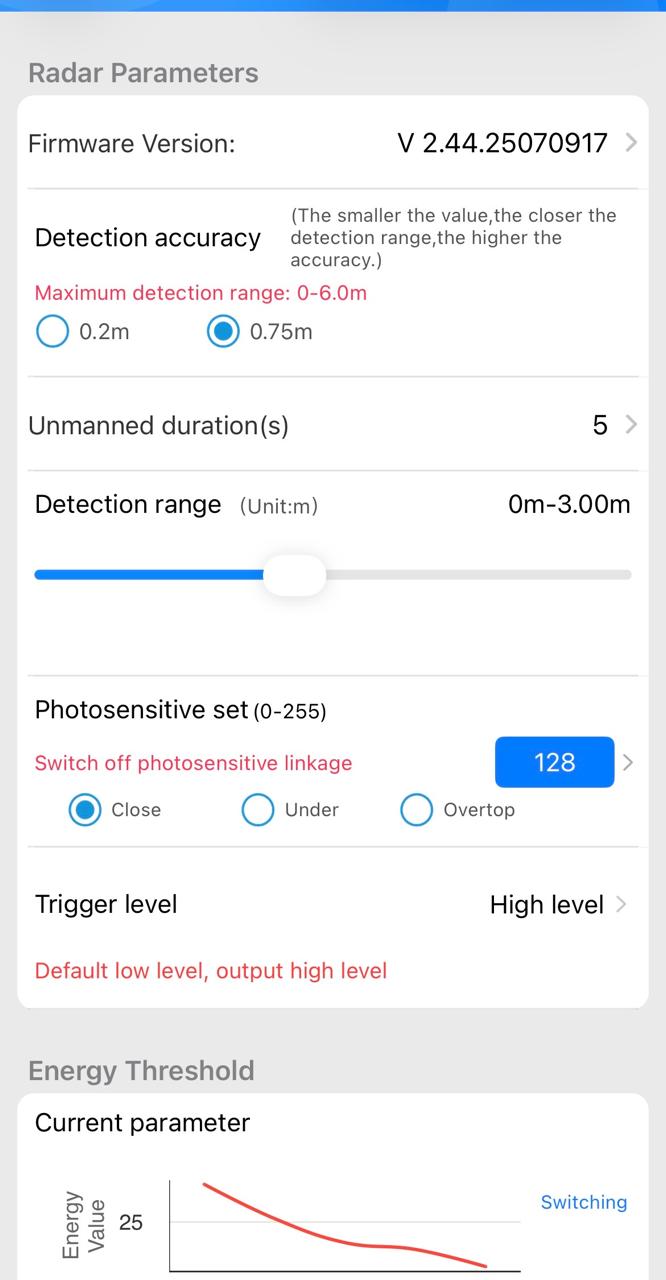
Firmware V 2.44.25070917 · Detection range 0–3 m

mmWave sensor configuration app: firmware version, detection range 0-3m, radar parameters
MR24HPC1 radar parameters via Seeed configuration app

mmWave sensor — live detection

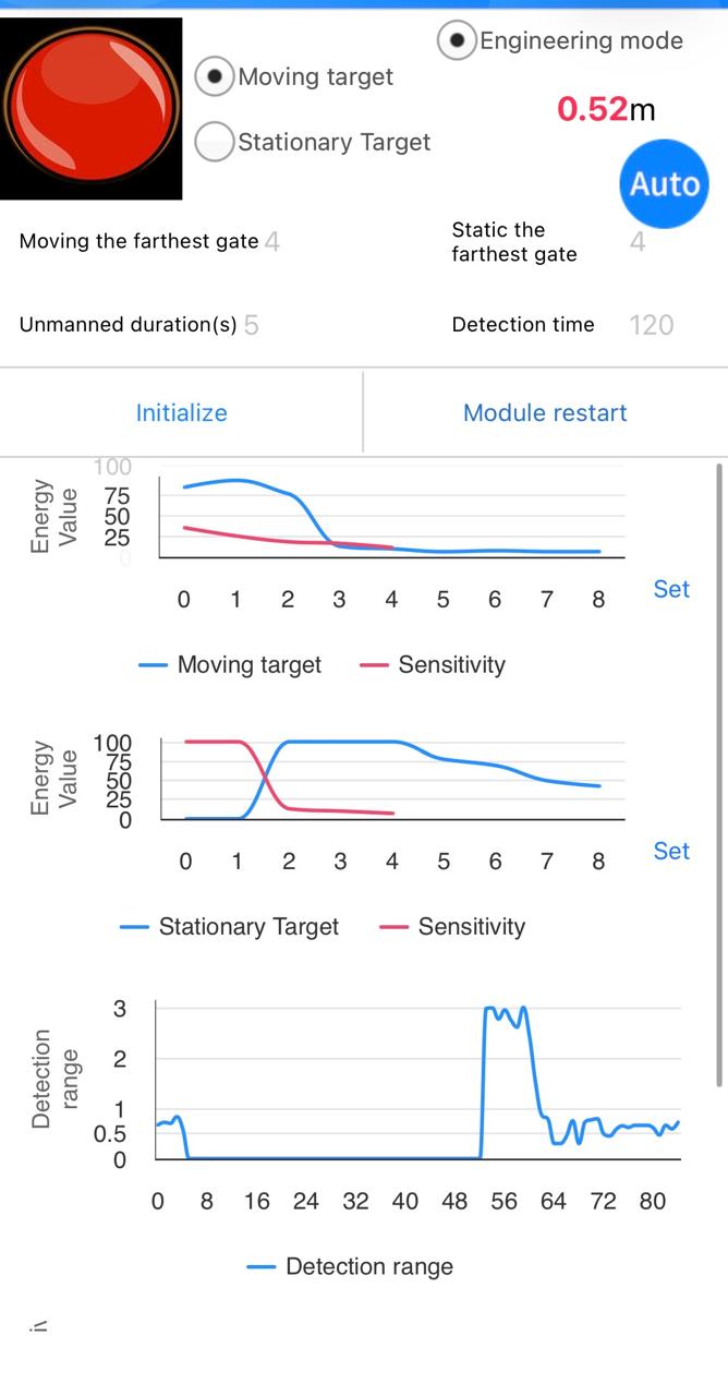
Moving target detected at 0.52 m · Engineering mode with per-gate energy graphs

mmWave live detection: moving target at 0.52m, energy value charts per distance gate
Live FMCW presence detection — moving + stationary energy values

Wire-up

ESP32-S3 GPIO43 (UART1 TX)  →  MR24HPC1 UART RX
ESP32-S3 GPIO44 (UART1 RX)  ←  MR24HPC1 UART TX
3.3 V                        →  MR24HPC1 VCC
GND                          →  MR24HPC1 GND
Design constraint: The ESP32-S3 has no hardware GPU or neural-network accelerator. All inference runs on the LX7 cores using INT8-quantized models via Espressif’s ESP-DL library. Per-frame inference takes 100–200 ms, motivating a lightweight, rule-based activation controller rather than a heavy deep-learning pipeline.

End-to-end system flow

Figure 3 — End-to-End System Data Flow
flowchart TD
    R["24 GHz mmWave Sensor"] --> P["Presence Trigger"]
    P --> C["ESP32-S3 Camera Capture"]
    C --> V["Vision Processing\nface/body/hand detection"]
    V --> T["Tracking Logic\nKalman filter"]
    T --> S["Servo Control\npan-tilt camera alignment"]
    V --> G["Gesture Recognition"]
    G --> A1["Open Palm:\nactivate microphone"]
    G --> A2["Closed Fist:\nstop recording"]
    G --> A3["Pointing:\ncapture object image"]
    A1 --> M["I2S Microphone Capture"]
    M --> D["Android Device\nspeech-to-text + AI response"]
    A3 --> D
    D --> U["User Feedback\naudio / response / action"]
    FT["CPRE 5450 Fault-Tolerance Layer"] -. monitors .-> P
    FT -. validates .-> C
    FT -. gates .-> G
    FT -. blocks/allows .-> M
    classDef sensor fill:#e6fffa,stroke:#319795,color:#111;
    classDef compute fill:#ebf8ff,stroke:#3182ce,color:#111;
    classDef action fill:#faf5ff,stroke:#805ad5,color:#111;
    classDef ft fill:#fff5f5,stroke:#e53e3e,stroke-width:2px,color:#111;
    class R,C,M sensor;
    class P,V,T,G,D compute;
    class S,A1,A2,A3,U action;
    class FT ft;
      

Proposed fault-tolerant design

Guiding principle: When uncertain, fail into non-activation, not unsafe activation. Ambiguity triggers a safe state, not an active state.

The proposed architecture treats activation as a fault-tolerant state machine. The mmWave sensor acts as a low-power sentinel. When radar indicates possible presence, the camera is activated briefly for confirmation. A fusion layer evaluates agreement, confidence, freshness, and timing health before allowing full activation.

Figure 4 — Fault-Tolerant Architecture
flowchart TD
    subgraph Inputs["Heterogeneous Sensor Inputs"]
        R1["mmWave UART Stream\npresence, distance gate, energy"]
        C1["Camera Frames\nvisual confirmation"]
    end
    subgraph Precheck["Input Integrity and Freshness Checks"]
        R2["Radar Parser\nframe header/footer, timestamp"]
        C2["Frame Quality Monitor\nbrightness, blur, timestamp"]
    end
    subgraph Diagnosis["Fault Diagnosis Layer"]
        D1["Cross-Sensor Consistency"]
        D2["Temporal Redundancy\nk-sample revalidation"]
        D3["Confidence and Health Score"]
        D4["Fault Classifier\ntransient vs persistent"]
    end
    subgraph Policy["Safe Activation Policy"]
        S0["Normal Activation"]
        S1["Soft Safe State\nretry and suppress activation"]
        S2["Hard Safe State\nblock activation + isolate input"]
        S3["Degraded Mode\nlimited low-power sensing"]
    end
    subgraph Outputs["Controlled Outputs"]
        O1["Allow camera inference"]
        O2["Allow audio capture"]
        O3["Allow servo movement"]
        O4["Notify user if persistent fault"]
    end
    R1 --> R2 --> D1
    C1 --> C2 --> D1
    R2 --> D3
    C2 --> D3
    D1 --> D2 --> D4
    D3 --> D4
    D4 --> S0
    D4 --> S1
    D4 --> S2
    D4 --> S3
    S0 --> O1
    S0 --> O2
    S0 --> O3
    S2 --> O4
    S3 --> O4
    classDef input fill:#e6fffa,stroke:#319795,color:#111;
    classDef diag fill:#fffaf0,stroke:#dd6b20,color:#111;
    classDef safe fill:#fefcbf,stroke:#d69e2e,color:#111;
    classDef out fill:#edf2f7,stroke:#4a5568,color:#111;
    class R1,C1,R2,C2 input;
    class D1,D2,D3,D4 diag;
    class S0,S1,S2,S3 safe;
    class O1,O2,O3,O4 out;
      

FreeRTOS Task Model

TaskCorePriorityFunction
mmwave_rx_taskCore 0High UART receive, CRC parser, freshness stamp
vision_taskCore 1High Frame capture, format, quality check, inference
ft_taskCore 0MAX-2 Consistency check, scoring, FSM transitions
web_server_taskCore 1Low HTTP dashboard, JPEG stream

The Task Watchdog Timer (TWDT) monitors ft_task for stalls. A stalled task that does not call esp_task_wdt_reset() within the 5-second watchdog period triggers a panic and is logged as a timing fault.

Confidence Score Fusion

Per-sensor confidence is computed each decision window:

Ci = ws · Si + wf · Fi + wt · Ti

  • Si — cross-sensor agreement (1.0 if agree, 0.0 if disagree)
  • Fi — freshness: max(0, 1 − (tnow − tsample) / Tstale)
  • Ti — transport health (1.0 if TWDT not triggered & no queue overflow)

Default weights: w_agreement = 0.50 · w_freshness = 0.30 · w_transport = 0.20

If C < min_confidence (default 0.60), activation is suppressed regardless of binary presence decision.

Runtime Sequence: Normal vs. Fault Handling

Figure 5 — Runtime Sequence Diagram
sequenceDiagram
    autonumber
    participant User
    participant Radar as mmWave Sensor
    participant ESP as ESP32-S3 Controller
    participant Cam as Camera Task
    participant Fuse as Diagnosis/Fusion Layer
    participant Act as Activation Outputs
    User->>Radar: Enters room or remains present
    Radar->>ESP: UART presence report + timestamp
    ESP->>Fuse: Radar state = present
    Fuse->>Cam: Request short visual confirmation
    Cam->>Fuse: Camera result + confidence + timestamp
    alt Radar and camera agree
        Fuse->>Act: Allow activation
        Act->>User: Interaction enabled
    else Temporary mismatch
        Fuse->>Act: Suppress activation
        Fuse->>ESP: Enter soft safe state
        ESP->>Radar: Request next sample window
        ESP->>Cam: Request another frame
    else Persistent mismatch
        Fuse->>Act: Block activation
        Fuse->>ESP: Enter hard safe state
        Act->>User: Notify uncertainty or fault
    end
      

Fault model & diagnosis logic

Fault Taxonomy

Faults are classified following Avizienis et al. (2004) along four axes:

By Source

  • Sensing faults — radar clutter, camera low-light, multipath
  • Communication faults — UART drops, PSRAM bus contention, DMA overrun
  • Timing faults — stale frames, over-long inference, watchdog events
  • Environmental faults — fan, curtain, reflective surface, sudden light change

By Duration

  • Transient — last one or a few decision windows; may self-resolve. E.g., brief radar glitch from a passing vehicle.
  • Persistent — persist across k_hard consecutive windows. E.g., camera initialization failure.
  • SDC-like (Silent Data Corruption) — sensor outputs appear valid but conflict with system state.
Figure 6 — Fault Taxonomy for the Activation Subsystem
flowchart TD
    F["Faults in Activation Subsystem"]
    F --> S["Sensor Faults"]
    S --> S1["Camera false negative\nlow light, blur, occlusion"]
    S --> S2["Camera false positive\nbackground mistaken as user"]
    S --> S3["Radar false positive\nfan, curtain, reflections"]
    S --> S4["Radar false negative\nrange-gate or orientation issue"]
    F --> T["Transport and Data Faults"]
    T --> T1["UART packet drop"]
    T --> T2["Radar framing error"]
    T --> T3["Stale timestamp"]
    T --> T4["Queue overflow"]
    F --> C["Computation and Timing Faults"]
    C --> C1["Camera task deadline miss"]
    C --> C2["Fusion task delay"]
    C --> C3["Watchdog event"]
    C --> C4["Memory pressure / frame loss"]
    F --> E["Environment / OOD Faults"]
    E --> E1["Low light"]
    E --> E2["Reflective surfaces"]
    E --> E3["Moving clutter"]
    E --> E4["Unexpected human posture"]
    F --> P["Policy-Level Failures"]
    P --> P1["False activation"]
    P --> P2["Missed activation"]
    P --> P3["Unsafe privacy-sensitive sensing"]
    classDef root fill:#e8f2ff,stroke:#2b6cb0,stroke-width:2px,color:#111;
    classDef category fill:#fffaf0,stroke:#dd6b20,stroke-width:2px,color:#111;
    classDef leaf fill:#f7fafc,stroke:#718096,color:#111;
    class F root;
    class S,T,C,E,P category;
    class S1,S2,S3,S4,T1,T2,T3,T4,C1,C2,C3,C4,E1,E2,E3,E4,P1,P2,P3 leaf;
      

Fault Detection Rules

Fault ClassExample Observable SymptomResponse
Camera false negative Low light / occlusion Radar present; camera absent Revalidate; soft safe state
Radar false positive Fan / curtain / reflection Radar present; camera no user Delay activation; request confirmation
UART / transport fault Dropped radar packet Missing/stale radar timestamp Parser reset; suppress activation
Timing fault Camera task delay Fusion uses stale frame Reject frame; watchdog recovery
Persistent sensor fault Camera init failure Repeated visual failure Hard safe state; isolate camera
SDC-like output Stale plausible data Valid-looking data conflicts with state Invariant check; rollback health state

Diagnosis Decision Flow (Per Decision Window)

Figure 7 — Per-Window Diagnosis Decision Logic
flowchart TD
    A["New Decision Window"] --> B{Radar data fresh and valid?}
    B -- No --> B1["Reject radar sample\nsoft safe or parser reset"]
    B -- Yes --> C{Camera frame fresh and valid?}
    C -- No --> C1["Reject camera sample\nsoft safe and retry"]
    C -- Yes --> D{Radar says presence?}
    D -- No --> E{Camera confirms user?}
    E -- No --> N["No activation\nidle low-power state"]
    E -- Yes --> F1["Disagreement:\npossible radar false negative"]
    D -- Yes --> F{Camera confirms user?}
    F -- Yes --> G["Agreement:\nallow activation"]
    F -- No --> F2["Disagreement:\npossible radar false positive or camera false negative"]
    F1 --> H{Mismatch count >= threshold?}
    F2 --> H
    B1 --> H
    C1 --> H
    H -- No --> S1["Soft safe state\nbounded revalidation"]
    H -- Yes --> S2["Hard safe state\nblock activation + isolate low-confidence input"]
    classDef decision fill:#ebf8ff,stroke:#3182ce,color:#111;
    classDef normal fill:#f0fff4,stroke:#38a169,color:#111;
    classDef warn fill:#fffaf0,stroke:#dd6b20,color:#111;
    classDef safe fill:#fff5f5,stroke:#e53e3e,color:#111;
    class B,C,D,E,F,H decision;
    class G,N normal;
    class F1,F2,B1,C1,S1 warn;
    class S2 safe;
      

Safe-state & recovery policy

Seven-State Activation FSM

IDLE
Low-power sentinel — radar only, camera off.
RADAR_CANDIDATE
Radar has indicated possible presence. Requesting camera.
VISUAL_CONFIRM
Camera confirmation in progress.
ACTIVE
Camera inference, audio capture, and servo actuation allowed.
SOFT_SAFE
Transient inconsistency. Full activation suppressed; retry.
HARD_SAFE
Persistent fault. Activation blocked; notify user.
DEGRADED
One sensor isolated. Minimal low-power operation.
Figure 8 — Activation State Machine
stateDiagram-v2
    [*] --> Idle
    Idle --> RadarCandidate: radar_presence_detected
    RadarCandidate --> VisualConfirm: request_camera_confirmation
    VisualConfirm --> Active: radar_agrees AND camera_confirms
    VisualConfirm --> SoftSafe: mismatch OR low_confidence OR stale_sample
    SoftSafe --> VisualConfirm: retry_within_time_window
    SoftSafe --> Idle: no_presence_after_retry
    SoftSafe --> HardSafe: mismatch_count >= N OR timeout_exceeded
    Active --> Idle: user_leaves OR session_complete
    Active --> SoftSafe: health_monitor_fault
    HardSafe --> Degraded: isolate_faulty_input
    Degraded --> Idle: manual_reset OR fault_cleared
    HardSafe --> Idle: watchdog_reset_completed
    note right of SoftSafe
        Temporary uncertainty
        Suppress full activation
        Revalidate radar + camera
    end note
    note right of HardSafe
        Persistent fault
        Block activation
        Notify user
        Preserve power and privacy
    end note
      
Soft Safe State

Transient Inconsistency

Full activation suppressed. System collects another radar sample and camera frame. If consistency is restored within soft_retry_ms (default 3000 ms), transitions back to Visual Confirm. Otherwise escalates to Hard Safe.

Hard Safe State

Persistent Inconsistency

Automatic activation blocked. Low-confidence sensor input isolated. User optionally notified via OLED/audio. Minimal power operation. Exit requires manual reset or watchdog-supervised sensor re-initialization.

Recovery Block for Visual Confirmation

Following the classical Randell (1975) recovery block pattern, visual confirmation uses a two-level fallback:

Figure 9 — Recovery Block Model for Visual Confirmation
flowchart TD
    A["Radar candidate detected"] --> P["Primary visual confirmer\nface/body detector"]
    P --> AT1{Acceptance test passed?}
    AT1 -- Yes --> OK["Accept visual confirmation"]
    AT1 -- No --> B["Backup confirmer\nsimpler motion or frame-difference check"]
    B --> AT2{Acceptance test passed?}
    AT2 -- Yes --> DEG["Degraded confirmation\nallow limited activation or retry"]
    AT2 -- No --> FAIL["No reliable confirmation\nenter safe state"]
    AT1 -. checks .-> C1["confidence >= threshold"]
    AT1 -. checks .-> C2["frame fresh"]
    AT1 -. checks .-> C3["ROI plausible"]
    AT2 -. checks .-> C4["motion consistent with radar"]
    classDef process fill:#ebf8ff,stroke:#3182ce,color:#111;
    classDef decision fill:#fefcbf,stroke:#d69e2e,color:#111;
    classDef ok fill:#f0fff4,stroke:#38a169,color:#111;
    classDef fail fill:#fff5f5,stroke:#e53e3e,color:#111;
    class A,P,B process;
    class AT1,AT2 decision;
    class OK,DEG ok;
    class FAIL fail;
      

Evaluation plan & metrics

Four Controllers Compared

Baselines
  1. Radar-only — activate on any radar presence signal, no confirmation
  2. Camera-only — activate on any face-detected frame
  3. Naive AND/OR fusion — no fault diagnosis; no safe states
Proposed

FT fusion — confidence scoring, cross-sensor diagnosis, transient/persistent classification, soft/hard safe states, recovery blocks

Fault Injection Tests

Fault TypeInjection MethodTarget Metric
Radar packet drops Drop 1-in-N UART frames randomly FAR, MDR, fault coverage
Radar framing error Corrupt SOF/EOF bytes Fault coverage, detection latency
Camera frame blackout Replace frame buffer with zeros MDR, soft safe state rate
Camera motion blur Convolve with Gaussian kernel Fault coverage
Induced timing delay vTaskDelay injection in sensor task TWDT trigger rate

Key Metrics

MetricDefinition
FAR — False Activation Rate Activations with no valid user / total trials
MDR — Missed Detection Rate No activation with valid user present / total trials
Fault Coverage Injected faults detected and correctly classified / total injected
Detection Latency Time from fault injection to fault flag (ms)
Activation Latency Time from user presence to first allowed activation (ms)
Soft Safe Entry Rate Fraction of trials that enter soft safe state

Expected Results

  • Lower FAR than radar-only — camera provides semantic rejection of clutter.
  • Lower MDR than strict AND fusion — transient faults enter soft safe state and retry.
  • Higher fault coverage than naive fusion — explicit disagreement diagnosis.
  • Moderate latency overhead (<500 ms) from soft-safe revalidation.

Comparative analysis

Capability Radar-only Camera-only Naive Fusion Proposed FT
Heterogeneous redundancy ✗✗✓ (implicit) ✓ (explicit)
Cross-sensor diagnosis ✗✗✗ ✓
Transient / persistent classification ✗✗✗ ✓
Soft / hard safe states ✗✗✗ ✓
Confidence / freshness scoring ✗✗✗ ✓
Fault-injection evaluation ✗✗✗ ✓
Timing fault detection (TWDT) ✗✗✗ ✓
Recovery block for vision ✗✗✗ ✓

Repository & API

Web dashboard

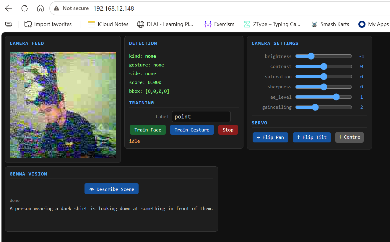
Served at the ESP32’s IP on port 80 after Wi-Fi connects. Shows live JPEG camera feed, detection state, training controls, camera settings, and servo controls.

MIRA web dashboard: camera feed, detection panel, training UI, servo controls
MIRA 2.0 web dashboard — camera feed, detection state, training, and servo controls

Key files

CPRE 5450 New
  • main/mmwave_sensor.h/.c — Seeed MR24HPC1 UART driver with CRC-8
  • main/ft_activation.h/.c — 7-state fault-tolerant activation FSM
Existing Platform
  • main/camera_control.h/.c — OV2640 init and frame capture
  • main/vision_pipeline.cpp — ESP-DL INT8 face detection
  • main/web_server.h/.c — HTTP dashboard (JPEG stream)
  • main/servo_control.h/.c — Pan-tilt PWM (LEDC)

FT Activation FSM — Public API

esp_err_t    ft_init(const ft_config_t *cfg);
ft_state_t   ft_update(bool radar_present, bool camera_present,
                        const mmwave_reading_t *radar, bool cam_fresh);
ft_status_t  ft_get_status(void);
bool         ft_activation_allowed(void);
void         ft_reset(void);
const char  *ft_state_name(ft_state_t s);

mmWave Sensor Driver — Public API

esp_err_t   mmwave_init(void);
void        mmwave_get_reading(mmwave_reading_t *out);
bool        mmwave_presence_detected(void);
bool        mmwave_is_stale(void);
uint32_t    mmwave_drop_count(void);

Default ft_config_t Parameters

ParameterDefaultDescription
w_agreement0.50Cross-sensor agreement weight
w_freshness0.30Data freshness weight
w_transport0.20Transport health weight
min_confidence0.60Minimum fused confidence for activation
stale_ms300 msFrame freshness deadline
soft_retry_ms3000 msMax time in Soft Safe before escalation
k_hard4Consecutive mismatches to trigger Hard Safe
k_window8Sliding window size for mismatch tracking
FT_TASK_INTERVAL_MS100 msFT task update period

Build & Flash

Requirements: ESP-IDF v5.x or v6.x (tested on Windows with PowerShell)

# Clone
git clone https://github.com/Shi6aSK/MIRA-2.0.git
cd MIRA-2.0

# Set up ESP-IDF environment (Windows PowerShell)
. $env:IDF_PATH/export.ps1

# Configure SSID/password in main/vision_config.h before building

# Build
idf.py build

# Flash and monitor (replace COM3 with your port)
idf.py -p COM3 flash monitor

The web dashboard is served at the ESP32's IP address on port 80 after Wi-Fi connects.

Bibliography

  1. A. Avizienis, J.-C. Laprie, B. Randell, and C. Landwehr, "Basic Concepts and Taxonomy of Dependable and Secure Computing," IEEE Trans. Dependable Secure Comput., vol. 1, no. 1, pp. 11–33, 2004.
  2. S. Li and R. Hishiyama, "An Indoor People Counting and Tracking System Using mmWave Sensor and Sub-sensors," IFAC-PapersOnLine, 2023.
  3. Y. Yu et al., "A Novel Multi-Source Sensor Correlation Adaptive Fusion Framework with Uncertainty Quantification for Intelligent Fault Diagnosis," Reliability Engineering & System Safety, vol. 267, 2026.
  4. M. Moradi and J. Denil, "Machine-Learning Assisted Model-Implemented Fault Injection," CEUR Workshop Proceedings, 2020.
  5. S. M. Kahya, M. S. Yavuz, and E. Steinbach, "HOOD: Real-Time Human Presence and Out-of-Distribution Detection Using FMCW Radar," IEEE Trans. Radar Systems, 2025.
  6. N. Zhang et al., "A Robust mmWave Radar Framework for Accurate People Counting and Motion Classification," Sensors, vol. 26, no. 4, 2026.
  7. B. Randell, "System Structure for Software Fault Tolerance," IEEE Trans. Software Eng., vol. SE-1, no. 2, pp. 220–232, 1975.
  8. H. Kopetz, Real-Time Systems: Design Principles for Distributed Embedded Applications, 2nd ed. Springer, 2011.
  9. Espressif Systems, ESP32-S3 Technical Reference Manual, 2023. espressif.com
  10. Espressif Systems, "Watchdogs," ESP-IDF Programming Guide, 2024. docs.espressif.com
  11. Seeed Studio, "24 GHz mmWave Sensor - MR24HPC1," 2023. wiki.seeedstudio.com